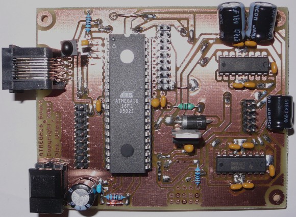
Microcontroller Board zur Steuerung von Fischertechnik Modellen
Hochgeladen am 8.1.2008, 21:21 von uffi. 5 / 21
Schlagworte: Microcontroller, PWM, Motor-Steuerung, Ausgänge, Sensor-Eingänge, Atmel, AVR, ATMEGA, Parallel, RoboPro, Interface, C, Programmierung, WinAVR, GCC, Assembler, AVR-Studio.
Features of this board are:
- 8 digital input/output ports (each equipped with an own ground line)
- 8 analog input ports (may also be configured as general purpose digital input/output ports, each equipped with an own ground line)
- 4 PWM controlled motor outputs with two L293DNE motor driver ICs
- Infrared remote control receiver SFH5110-38kHz (example: use of your television remote control with RC5/RC6 code for commands to the µC board)
- Communication to a second identical board in SPI (serial peripheral interface) mode with slave select via RJ-45 modular cable connection (patch cable)
- Communication to up to 127 devices via I2C interface protocol implemented in software on any two digital ports (example: connect other µC boards or I2C devices such as ultrasonic distance sensors), see the I2C software library by Peter Fleury for integration in WinAVR GCC, especially the pure software implementation with “i2cmaster.h” and “i2cmaster.S”
- 8 bit µController ATMEGA16 (or pin compatible ATMEGA32 or ATMEGA8535)
- Up to 8 MHz internal RC oscillator clock or 16 MHz with optional quartz crystal resonator (not included in part list or placement view, insert “free flying” at two solder pads next to XTAL pins)
- Code may be written in C with WinAVR GCC (Gnu C-Compiler, free download) or in + Assembler with AVR Studio (free download from Atmel web site)
- Code may be downloaded to the internal code-flash memory via the parallel port of your computer (see below the board “programmer”). For this you need an old fashioned legacy type PC with parallel printer port (they become pretty rare these days).
- During code download, the board must be powered. Either with an external source via the voltage regulator, or via the parallel port of the PC (the metal bridge J3 on the board “programmer” must be inserted). However, current supply via the parallel port of the PC is limited to a few mA. Therefore, the jumper JP1 on the board “ATMEGA16” must be opened to disconnect power supply for the L293DNE’s during downloading, since they draw 20mA each even if inactive.
see also:
http://home.arcor.de/uffmann/Electronics.html#Chapter5
uffi (10.1.2008, 13:24:15)
Weitere Infos zu dem Board incl. Download der Eagle Dateien zum Nachbau der Platine sowie template für ein C-Programm mit Setup der Pin-Konfiguration gibt es hier:
uffi (10.1.2008, 13:27:59)