Du baust gerne mit fischertechnik? Hier gibt es für dich ….
- eine Bildersammlung (schau dir Fotos anderer fischertechnik-Freunde an und nutze sie als Vorbild für eigene Modelle)
- einen Servicebereich (lade Bauanleitungen und andere Dokumente herunter)
- ein Forum (tritt in Kontakt mit Gleichgesinnten)
- die kostenlose Zeitschrift ft:pedia (mit Artikeln und Modellvorstellungen)
- Veranstaltungen, bei denen du vor Ort erlebst, was mit fischertechnik alles möglich ist.
Weitere aktuelle Infos dazu auch im Forum.
- 12.-13. Oktober 2024: ftc:süd:con:24 im Fördertechnik Museum Sinsheim
- eine Teile-Datenbank (nutze die umfangreichen Informationen über aktuelle oder frühere Bauteile und Baukästen sowie Bauanleitungen und andere Dokumente)
20.09.2025
- 20.09.2025
ftc-Convention 2025 - fischertechnik baut Brücken Martinskirche Bad Hersfeld

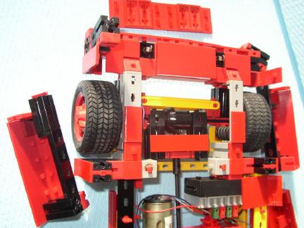
Neu im Bilderpool
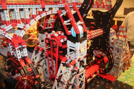
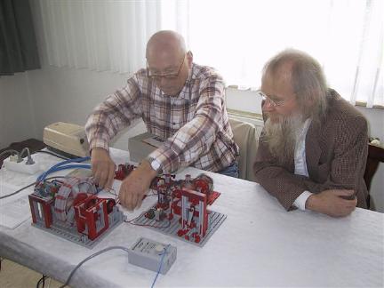
Aus unserem Bilderpool
Aus unserem Bilderpool