The user interface
Hochgeladen am 10.2.2014, 22:32 von rubem. 8 / 17
Schlagworte: Interface, Arduino, .NET, C#, script, language.
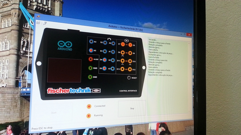
Finally, here is the user interface running in my computer. I don’t have much time to fiddle with microcontroller software anymore, so the Arduino sketch is pretty basic: it’s essentially a dumb USB serial interface to the much more powerful .NET / C# software (depicted here) which does the actual work. I’ve used a simple script language that allows me to monitor the inputs (shown in blue) and control the motors (yellow). As you can see, this hardware has ten inputs and can control up to four motors, so I believe it’s roughly equivalent to the old serial interface or the Robo interface. Of course neither fischertechnik nor Arduino allowed me to use their logos, but this is for personal use only so I believe they won’t mind ;)
Stefan Falk (11.2.2014, 10:58:11)
Welcome onboard, Rubem! Deep respect for the whole, brilliant work, and best regards to Brazil!
Now, my questions: a) What exactly did you replace on the gear? b) How does this .net/some-scripting-language-usb-ardunio thing work together? What scripting language do you use?
Stefan
rubem (11.2.2014, 13:32:07)
Hi, and thank you for the compliments! I’ve just posted another pic showing the details of the turntable drive, so I hope it’s clearer now. And I promise I’ll write a more detailed explanation about the interface in a couple of days.
rubem (12.2.2014, 18:18:45)
Okay, here is a detailed explanation. Here is how it works: The switches and sensors are hooked directly to the Arduino inputs. The motors are driven by four BA6418N motor drivers, each connected to a pair of Arduino outputs. The Arduino just acts as a dumb I/O interface, it has no intelligence of its own. So the Arduino sketch is very simple, only about 100 lines long. First it sets up the USB serial protocol and pin I/O modes. The loop does two things: it scans the inputs and writes the values to the USB serial port, then checks the serial port for available commands and sets the output pins (which are connected to the motor drivers) accordingly. That’s the end of the Arduino part.
The .NET/C# application (depicted above) runs a simple custom script language. Here is a snippet which should (hopefully) be self-evident:
print ‘Starting…’
if not input_A5 // That’s the photocell call swivel_to_front [] endif
call open_gripper []
while 1 call wait_object [] call close_gripper [] call swivel_to_back [] call open_gripper [] call swivel_to_front [] endwhile
proc swivel_to_front [] println ‘Swiveling arm to front’ set motor_4 ’left’ // Output values are sent to the serial interface while not input_A5 // Input values are received from the serial interface end_while set motor_4 ‘stop’ println ‘Done.’ endproc
…
This should be best done with a real embeddable language like Lua, but I already had the script code at hand because I’m presently developing it for a commercial project.
The C# app also shows the state of the various inputs and outputs as you can see above. Active I/O pins are in red.
Whatever is the script language, the advantage of this approach is that I don’t have to compile my C# app nor fiddle with Arduino sketches all the time, I can easily write and test scripts with my text editor without compiling anything. Just edit, save, and press the Start button. The obvious disadvantage of this approach is that the setup must be always hooked to a PC to run even this simplest script! So any mobile robots or vehicles must be connected by ribbon cable :)
I hope this cleared it!